Work done on the design of Lares-2
Contents:
1. Introduction
2. Retroreflectors
3. Configuration of the satellite
4. Temperature of the core and retroreflectors
5. Thermal analysis of the retroreflectors
6. Recalculation of the the thermal analysis
7. Conclusions
1. Introduction
The work began in March, 2016 and ended in Oct, 2018. I stopped working
for ILRS at the end of November, 2018. I wrote detailed reports on the
Lageos-1, Lageos-2, and Lares-1 satellites. Since I no longer work for ILRS,
I do not expect to write a similar report for Lares-2.
However, there are a large number of short reports plus many emails
describing the work that I did on the design. I am accumuating these documents
into a file. The document below gives a partial list of emails and short reports.
I am still in the process of finding more documents and adding them to the file.
List of documents
The Lares-2 satellite needed to be completely redesigned to meet the current
one millimeter accuracy goal for the ITRF and earth physics studies. The main
problem is that the 1.5 inch cubes used on the Lageos-1, Lageos-2, and Lares-1
satellites are too large. The optimum size is one inch.
2. Retroreflectors
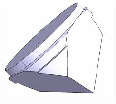
Below is a picture of an uncoated 1.5 inch retroreflector such as used on Lageos
There are mounting tabs for holding the retroreflector in its cavity.
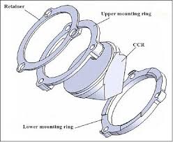
Retaining rings are used to hold the Lageos retroreflector
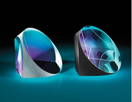
Lares-2 will use COTS retroreflectors. The picure below shows a COTS retroreflector.
On the left is an uncoated retroreflector. The one on the right is coated.
There are no mounting tabs. A new holder had to be devised for Lares-2.
Testing shows that the COTS retroreflectors have the same optical quality as
much more expensive custom made retroreflectors.
3. Configuration of the satellite
The bulk of the work done on the design consisted of analyzing dozens of possible
configurations with different diameters of the sphere, number of retroreflectors, ways of
distributing the retroreflectors, and where to place holes for attaching the satellite to
to the deployer that holds the satellite in the launch vehicle. The options were limited
by the desire to use the same deployer used on Lares-1.
On Lageos-1, Lageos-2, and Lares-1 the retroreflectors are arranged in rings. The paper
Thermal Optical Design of a Geodetic Satellite for One Millimeter Accuracy
gives the analysis of a configuration with 288 retroreflectors on a 20.1 cm radius sphere.
The systemstic error due to the distribution of retroreflectors is estimated at .4 mm
The need to provide holes to attach the deployer disrupts the uniformity of the coverage
by the retroreflectors. Since the rings are at equal inervals in Latitude, there may not
be enough space between the rings to accomodate the holes for the deployer. It is not
necessary to have a ring structure. The retroreflectors only need to be placed so as to
to provide uniform coverage.
The systematic error for a particular configuration is estimated by computing the range
correction at a large number of incidence angles on the satellite. The range
corrections are plotted vs Latitude on the satellite. The plot is averaged over 5 deg
intervals in Latitude to estimate the systematic error. The Latitude may be measured
from any of the three X,Y,Z axes. The symmetry axis shows the largest variation due to
the placement of the holes for the attachment to the deployer.
I presented a poster on the design at the ILRS Technical Workshop in Riga, Latvia held
October 2 - 5, 2017. The phrases in red are last minute suggestions by Reinhart Neubert.
Poster on the design of Lares-2
On April 3, 2018 I received the email below regarding a possible change to
copper for Lares-2. Copper has a much higher thermal conductivitiy.
Possible change to copper
On April 5, 2018 I sent the email below summarizing the results of the analysis.
Summary of the results
The file below gives the details of the analysis.
Comparison of two configurations.
The analysis shows that both configurations meet the accuracy requirement.
The Colatitude is measured from the X-axis which is the symmetry axis.
The systematic error increases to about .8 mm due to the need to accomodate the
deployer. This is within the one millimeter goal.
The full list of coordinates for the two configurations is given below.
First array
Second array
The file below gives a similar analysis for a configuraion from Nov 25, 2017. This
file gives some additional analysis of the effect of removing a retroreflector
in order to accomodate attachments to the deployer. Removing a retroreflector changes
the range correction by about one millimeter when the incidence angle is directly
over a missing retroreflector. This does not change the average range correction much.
Analysis including the effect of a missing
retroreflector
At the time this analysis was done, it was expected to be the final configuration.
Another "final" analysis was done on December 13, 2017. The Z-axis is the symmetry axis.
Analysis done December 13, 2017
4. Temperature of the core and retroreflectors
On April 26, 2018 I received the URGENT message below.
Urgent message from Antonio
I replied in the following message.
Reply to Antonio's message
This problem indicated a need to calculate the temperature of the core and the
retroreflectors from the physical parameters. This information is important not
only for calculating thermal effects on the retroreflectors, but also for doing
the thermal thrust calculations. Ideally the satellite should be isothermal and cold.
The retroreflectors should be as cold as possible to minimize thermal gradients.
Since there did not seem to be any readily available way to calculate the
temperature of the core and retroreflectors, I decided to derive equations
assuming both the core and the retroreflectors are approximately isothermal.
Richard Matzner kindly agreed to check the equations. He did not find any
errors. His reply is below.
Reply from Richard Matzner
The equations and examples are given in sections 7 and 8 of the paper below.
Thermal Optical Design of a Geodetic Satellite for One Millimeter Accuracy
In order to keep the satellite as cold as possible it would be desirable to have
the a/e of the satellite be as low as possible. There is available technology
to do this using OSR coatings. I discussed this with Erricos Pavlis.
Discussion of using an OSR coating
The following company in Italy manufactures such coatings.
OSR thin films
5. Thermal analysis of the retroreflectors
Contents of section 5:
5.1 Introduction
5.2 New method of determining the effect of thermal gradients
5.3 Thermal case 12, Aug 4, 2017, strong thermal contact
5.4 Comparison with Case 11, computed Aug 5, 2017, floating mount
5.5 Cases 16,17 - emissivity of the cavity
5.6 Comparison of Case 17 (high emissivity) with Case 11 (low emissivity)
5.1 Introduction
One of the most serious sources of error in the range correction for a retroreflector
array with solid retroreflectors is thermal gradients in the glass. Because the index
of refraction is generally a function of temperature, the phase front is distorted as
the laser pulse passes througth the glass. This distorts the diffraction pattern. The
change in the strength of the signal from each retroreflector changes. This changes the
range correction. As the thermal conditions change in orbit, the range correction changes
with time.
The way to fix this is to design the array so that the temperature remains as constant
as possible. The thermal studies done on Lageos-1 recommended isolating the core from the
retroreflectors by using a floating mount and a low emissivity cavity. Laboratory testing
of the 1.5 inch retroreflectors used on Lageos-1, Lageos-2 and Lares-1 shows significant
changes in the diffraction pattern. Since the thermal problems go as a power of the size
(approzimately fourth power), I recommended reducing the size of the cubes to 1.0 inches.
I have written a thermal simululation for doing parametric studies of retroreflectors.
It has a generic model of mounting rings. The Italian team doing the design of Lares-2
wrote a high fidelity simulation of their mount design using commercial software.
The analysis proceeds in the following stages:
1. Compute the temperature distribution in the retroreflector.
2. Do a ray tracing to get the exiting phase front.
3. Add phase changes due to dihedral angle offsets.
4. If the retroreflector is uncoated add phase changes due to total internal reflection.
5. Perform a fast Fourier transform of the wave front to compute the FFDP
(Far Field Diffraction Pattern).
6. Analyze the FFDP to determine the variation of the energy within the part of the
pattern determined by the velocity aberration. For the Lageos altitude this is the
annulus between about 32 and 40 microradians.
Step 1 is done by program THERMAL or program THERMAL2. The second program has a generic
model for retaining rings. A commercial software package would need to be used to get
numerically accurate results for the temperature distribution in a retroreflector. This
program is used only for paramatric analyses to determing the effect of various parameters
to optimize the design.
Step 2 is done by program RAYTRACE. This program reads the temperature matrix produced
in step 1. The ray tracing is done to determine the phase changes due to thermal gradients.
Steps 3, 4, and 5 are done by program DIFRACT. This program reads the phase matrix computed
by program RAYTRACE. The phases due to thermal gradients, dihedral angle offsets, and
total internal reflection are added to determine the complex phase front. If there is
no total internal reflection, the phase front has only real components. The output is
the far field diffraction pattern matrix.
Step 6 is done by various programs to plot the pattern or do various averages over the
annulus of the far field pattern determined by the velocity aberration.
Dr. Reinhart Neubert who participated in the design has also written software for doing
the ray tracing and computation of the far field diffraction pattern. Comparison of our
results shows good agreement.
The file below dated July 22, 2017 is an example of the kind of parametric analysis
that can be done with the program.
The effect of mount conductance
This analysis shows how the mount conductance affects the temperature and diffraction
pattern of the retroreflector. The effect of mount conductance saturates as the
temperature of the retroreflector approaches the temperature of the mounting cavity.
5.2 New method of determining the effect of thermal gradients
A new method has been invented for evaluating the effect of thermal gradients.
The effect of dihedral angle offsets is symmetrical for + and - offsets in the
absence of a thermal gradient. For this reason, having a zero mean dihedral angle
offset reduces the effect of random errors by a factor of two.
However, when a thermal gradient is added, + and - offsets give different results.
In general, the phase front tends to be predominantly either convex or concave.
If a convex phase front is added to a concave phase front the phase fronts tend to
cancel each other. Conversely, if the phase fronts have the same curvature they add
to each other. Adding the phase front due to a thermal gradient to the phase front
from a dihedral angle offset will either decreae or increase the beam spread
depending on whether the curvatures are the same or opposite.
This effect has been used to evaluate the effect of thermal gradients for the size of
the measured random errors in the dihedral angle offsets of COTS retroreflectors.
The FFDP is computed for three cases:
1. Isothermal
2. Thermal with a + dihedral angle offset
3. Thermal with a - dihedral angle offset
The three cases are plotted together. The difference between cases 2 and 3 is used
as a measure of the effect of the thermal gradient.
The Italian team computed temperature distributions for a number of cases. The most
important cases are 11, 12; and 16, 17.
5.3 Thermal Case 12, Aug 4, 2017, strong thermal contact.
On August 4, 2017 I received the temperature matrix for Case 12 (email below).
Temperature matrix for Case 12.
This case is for strong thermal contact with the retroreflector. This goes against
the recommendations of the Lageos study that recommended a floating mount. The reason
for studying this case is that it would solve certain mechancal problems. The results
of the optical analysis are given in the document below.
Optical simulation for Case 12.
The results show significant degragation of the diffraction pattern. The email below
summarizes the results.
Discussion of Case 12.
5.4 Comparison with Case 11, computed Aug 5, 2017, floating mount.
The file below shows a comparison of Case 12 with Case 11 that uses a floating mount.
Calculation of Cases 11 and 12.
The email below discusses the results of the comparison.
Email discussing the comparison.
5.5 Cases 16,17 - emissivity of the cavity
The two materials considered for the core of the satellite were a nickel alloy and a
copper alloy. The copper has a better conductivity but a higher emissivity. The higher
emissivity goes against the recommendations of the Lageos study that recommended
low emissivity.
On February 15, 2018, I received the following request to analyze Cases 16 and 17.
Request to analyze Cases 16 and 17
Later that day I received the email below from Reinhart Neubert.
Email from Reinhart Neubert
His analysis is given in the file below.
Thermal analysis by Reinhart Neubert
Antonio Paolozzi was happy with the results. His response is below.
Response from Antonio Paolozzi.
Case 17 gives a small change for one dihedral angle offset but not for the other.
This is not acceptable since the thermal conditions vary in orbit. Also it would
require purchasing a large number of retroreflectors and selecting only the ones
that have a particular offset by chance.
There was various discussion back and forth about this problem (See email below).
Discussion about the emissivity problem.
Antonio makes the following point: "In the hypothesis of uniform emissivity all over
the satellite, the flux from the metallic cavity is independent on the value of the
emissivity." In fact, this is a complex system with a variety of different parameters
for the various parts. I later derived equations for computing the temperature of the
core and the retroreflectors as a function of the physical parameters.
On March 23, 2018 I sent the email below to Antonio Paolozzi.
Email regarding Cases 16 and 17
The attachment is below.
Analysis of Cases 16 and 17.
5.6 Comparison of Case 17 (high emissivity) with Case 11 (low emissivity)
The email below dated September 15, 2018 summarizes the results of the comparison.
The thermal effects for case 17 are 4 times greater than for case 11.
Email summarizing the comparison.
Analysis of Case 17 vs Case 11.
6. Recalculation of the thermal analysis
There was an error in the thermal analysis in Section 6 of the Canberra paper. The
file below explains the error and gives corrected calculations. Fortunately, the
conclusions of the study remain the same.
Recalculation of the thermal analysis
The glass used for a solid retroreflector has a very high emissivity. The radiation
emitted from the front face is proportional to the fourth power of the temperature.
This is the dominant factor in creating a temperature gradient at the front face.
The fractional change in cross section is plotted vs temperature in the file above.
7. Conclusions
A. The best way to minimize thermal effects is to keep the retroreflector as cold as possible.
B. One inch uncoated retroreflectors give the best uniformity of the range correction.